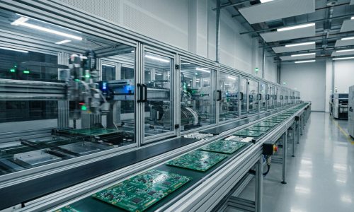
Surface mount technology (SMT) involves attaching electronic components, known as surface mount devices (SMD), directly onto the surface of a printed circuit board (PCB). SMT is popular in the industry due to its cost-effectiveness and quality efficiency.
What is Surface Mount Technology (SMT)?
Surface mount technology is a method of assembling and producing electronic components directly on the surface of a printed circuit board (PCB). This process facilitates automated production, handling more of the necessary assembly to create a functioning board. Components mounted in this manner are called surface-mount devices (SMD). Unlike traditional assembly methods, SMT doesn’t require components to be inserted through holes; instead, components are soldered directly onto the board via reflow soldering.
Initially named Planar Mounting, SMT was developed by IBM in the 1960s for building small-scale computers, replacing the older Through-Hole Technology. However, it wasn’t until 1986 that SMT gained significant traction, reaching 10% market adoption. By 1990, surface-mounted devices (SMDs) were prevalent in most high-tech printed circuit assemblies (PCAs).
SMT components feature small tabs for soldering, allowing them to attach to the PCB surface. In the era of Through-Hole Technology, components were mounted through lead holes drilled into PCBs, which were sized to fit each component snugly before soldering. With SMT, the drilling step is skipped, and SMDs are quickly sorted and attached to the top of the PCB, significantly reducing the device assembly process.
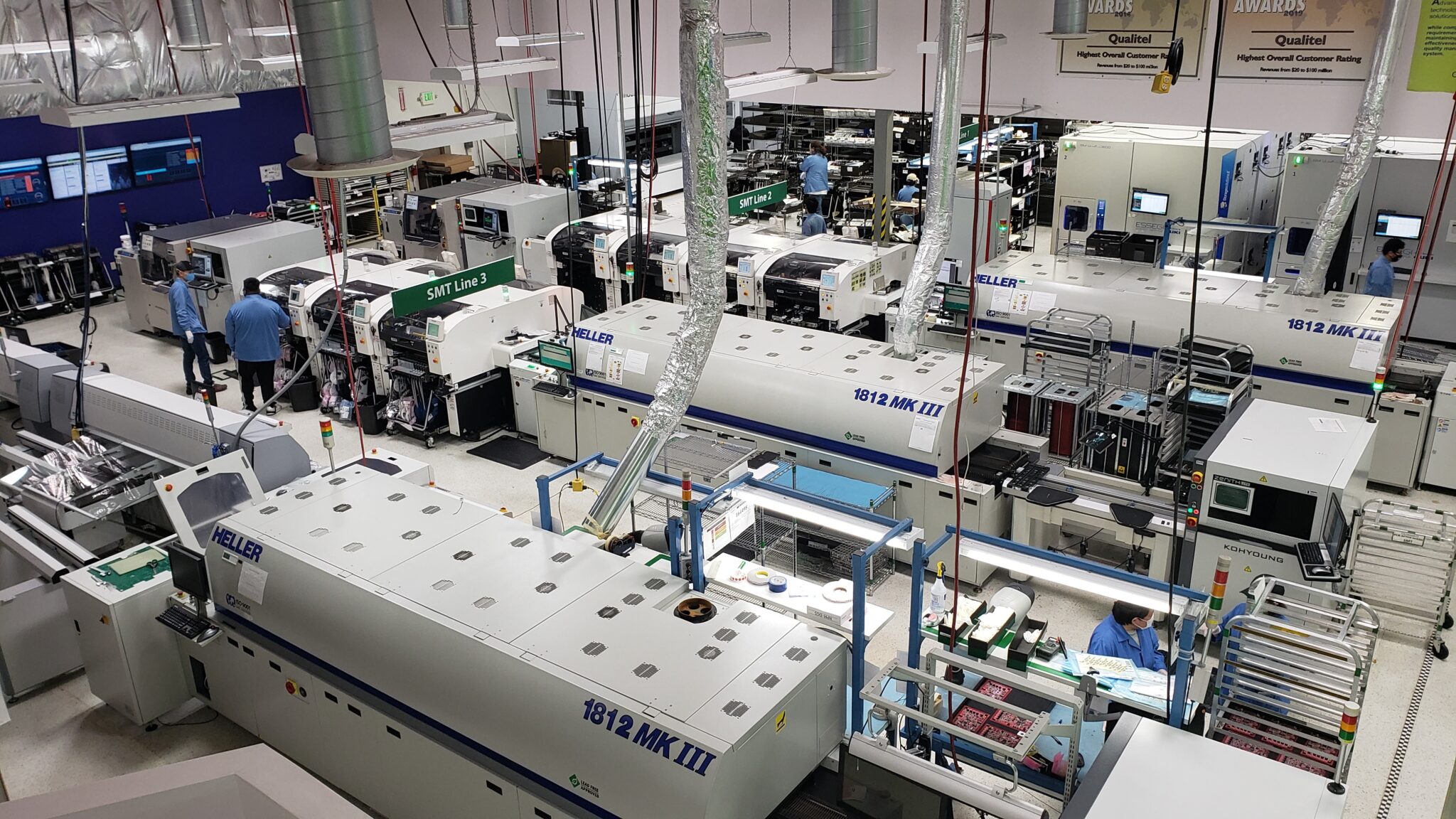
The SMT assembly process can be painstaking and time-consuming if done manually, requiring high precision for creating high-quality surface mount assemblies (SMA). Therefore, most SMT manufacturing is carried out using automated assembly machines, especially for large-scale production.
SMT components are much smaller than through-hole components, enabling the production of sleek and modern electronic devices. Nowadays, SMT is used in almost every electronic device, from toys and kitchen appliances to laptops and smartphones.
SMT Manufacturing Process
The SMT manufacturing process is split into three main stages: solder paste printing, component placement, and reflow soldering. Let’s break it down further:
1. SMC and PCB Prep
First things first, you pick out the SMCs and design the PCB. The board usually has flat, shiny pads made of silver, tin-lead, or gold-plated copper, known as solder pads. These pads support the pins of the components like chips and transistors.
A crucial tool here is the stencil. It helps position the solder paste in the next step. The stencil aligns with the solder pads on the PCB. It’s important to check these materials for any flaws before moving forward.
2. Solder Paste Printing
This step is super important. A printer uses the stencil and a squeegee (a tool for spreading) at an angle between 45° and 60° to apply the solder paste. The paste is a mix of powdered metal solder and sticky flux. The flux acts as a temporary glue and cleans the soldering surfaces, removing impurities and oxidation.
The solder paste is used to connect the SMC and the solder pads on the PCB. Each pad needs just the right amount of paste. If not, the connections won’t form properly when the solder melts in the reflow oven. In electronics manufacturing, a reflow oven is a heating device used in SMT to place electronic components on PCBs.
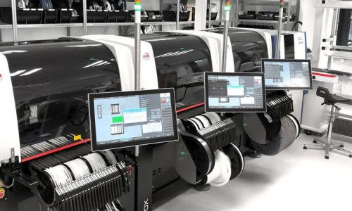
3. Component Placement
Next up, pick-and-place machines come into play. These machines grab each component using a vacuum or a gripper nozzle and place it in the correct spot on the PCB. The PCB moves along a conveyor belt while these machines quickly and precisely place components, some handling up to 80,000 parts per hour.
Precision is key here because any misplaced component that’s soldered in the wrong spot can be a pain to fix.
4. Reflow Soldering
After placing the SMCs, the PCB goes into the reflow soldering oven. Here, it moves through different zones to complete the soldering:
Preheat zone: In this first section, the board and all components are gently warmed up together. The temperature rises steadily, around 1.0℃-2.0℃ per second, until it hits between 140℃ and 160℃.
Soak zone: The board then sits in this zone for about 60-90 seconds, staying at a steady temperature between 140℃ and 160℃.
Reflow zone: Next, the temperature cranks up quickly, again at 1.0℃-2.0℃ per second, reaching a peak of 210℃-230℃. This melts the solder paste, causing the component leads to bond with the PCB pads. Surface tension of the molten solder keeps the components in place during this process.
Cooling zone: Finally, the board enters the cooling area, where the solder solidifies quickly to prevent any joint defects.
If the PCB is double-sided, these steps might be repeated with either solder paste or glue to secure the SMCs on both sides.
5. Cleaning and Inspection
After soldering, the board needs a good cleaning and thorough inspection. Any flaws found are fixed, and then the product is stored. Common inspection methods include magnifying lenses, AOI (Automated Optical Inspection), flying probe testers, and X-ray inspection. These tools, rather than the naked eye, provide quick and precise results.
Soldering of PCB with Electronic Components
SMT: Pros and Cons
SMT has a lot going for it when it comes to PCB assembly, manufacturing, and electronics production. Here’s why it’s a game-changer:
- Enables the use of smaller components
- Boosts automation in the manufacturing process
- Offers maximum flexibility in PCB design
- Enhances reliability and performance
- Reduces the need for manual component placement
- Produces smaller, lighter boards
- Simplifies PCB assembly, allowing both sides of the board to be used without the need for holes
- Can work alongside through-hole components, even on the same board
- Increases component density, fitting more SMDs in the same space or the same number in a smaller area
- Lower material costs
- Streamlines production and cuts costs
But, like everything, SMT has its downsides too:
- Small size can be a disadvantage
- Components are fragile and can break easily
- Requires high precision in soldering techniques
- Components can be easily misplaced or damaged during installation
- Visual inspection is tricky and testing is challenging
- Miniaturization and many solder joint types make the process and inspection more complex
- Requires significant investment in equipment like SMT machines
- Technical complexity demands extensive training and learning
- Rapid advancements necessitate continuous updates
SMT vs SMD
People often mix up SMT and SMD, using them interchangeably. It’s easy to see why—technology and its components can get pretty intertwined, causing confusion. That’s why it’s key to understand the difference between SMT assembly and SMD components.
To keep it simple, SMT refers to the process and technology, while SMDs are the actual devices involved. SMT is the method of placing and soldering electronic components directly onto a PCB. These components, known as surface mount devices (SMDs), are designed to be mounted on a printed circuit board.
SMDs allow for faster production, more flexibility, and lower costs, all without compromising functionality. They enable more circuits to fit in a smaller space, making devices more compact. This miniaturization is a standout feature of SMDs.
SMT and SMD work hand in hand to deliver quicker, more efficient, and more reliable PCBs.
Closing Thoughts
The main attractions of SMT are its smaller size, faster production, and reduced weight, making electronic circuitry design and production much easier, especially for complex circuits. This higher level of automation has saved time and resources in the electronics manufacturing industry. While there’s always the potential for new technology to emerge, SMT has firmly established its importance.